

Automotive Wiring Harness Design for Electric Vehicles
Time : October 30, 2026 View : 254
Automotive Wiring Harness Design for Electric Vehicles
An EV harness drawing needs an installation check before release. Can you reach the latch with the surrounding hardware fitted? What happens to the motor-side branch as the powertrain moves? Your automotive wiring harness design is incomplete until you can answer both. We work from the circuit to the installed assembly, using the prototype to check what the drawing missed.
A circuit list gives every branch a purpose
Your circuit list establishes what each connection must carry. Record the source, destination, pin assignment, operating voltage, continuous current and relevant transient loads. Include the return path. Give the assembly team a circuit identifier that traces back to these requirements.
Give each circuit a place in the vehicle. Sharing a compartment does not make an auxiliary supply, a control circuit and a traction connection one bundle. Your custom automotive wiring harness needs a grouping decision for each branch before you order the sleeves.
Interface details deserve their own drawing checks. Show whether a connector view looks into the mating face or the wire-entry side, and identify cavity numbers. A mirrored pinout can produce a neatly assembled harness with the wrong connections. Your schematic and connector schedule must tell the same story.
High-voltage routes need a complete connection design
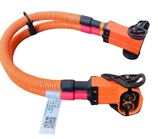
Take a high voltage wire harness between a battery and inverter as an example. The cable route ends at those interfaces, whose connector requirements become part of the design. Our EV assemblies at Songyuan wiring harness cover connections for batteries, inverters, drive motors and onboard chargers. Bring the interface drawings to the configuration discussion.
Choose the cable against the load it will carry in its installed position. Current, conductor resistance, ambient heat and bundling affect the thermal assessment. Check voltage drop along the complete current path. Upsizing the conductor can force you to change the terminal or leave more room for the cable to turn.
A shield drawn around the cable also needs a defined connection at the equipment. Your drawing should show that connection and identify sensitive signal wiring near the power route. If your vehicle uses an interlock, follow that circuit across the interfaces too. Assign separate checks to the shield connection, seal and interlock circuit.
For this family of high-voltage assemblies, we offer 6–150 mm² conductor options. There is no single current rating for that whole range: your electrical and thermal assessment determines the size to specify. Keep the cable and contact temperature limits with the installation assumptions in the design record.
Outer diameter turns the schematic into a packaging problem
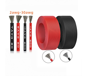
Your route needs the finished wire diameter, including insulation. At a grommet, compare the opening with the bundle envelope. For a terminal seal, check both ends of the permitted insulation-diameter tolerance. Add the sleeve and shield thickness, and check the bulk where branches leave the bundle.
Our extra-soft silicone rubber insulated wire comes in sizes with quite different outside dimensions. The dimensions below help with packaging calculations. Automotive suitability needs a separate assessment for the selected circuit.
|
Extra-soft wire option |
Outer diameter |
Packaging implication |
|
20 AWG |
1.8 ± 0.1 mm |
Check small seals against the diameter tolerance |
|
16 AWG |
3.0 ± 0.1 mm |
Allow additional space at branch exits |
|
10 AWG |
5.5 ± 0.25 mm |
Check connector entry and bundle clearance |
A hand-bent sample tells you little about how long a moving branch will last. Compare the cable specification with the bend, fluid exposure and temperature at its installation point. A clamp that forces a tight bend still needs moving.
Connector access determines where branches can end
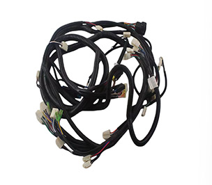
Connector placement must allow the actual assembly movement. Check the space your technician needs to mate the connector and close its locks. Try that operation with the surrounding parts fitted, not just in an empty compartment.
Branch length must accommodate motion without creating a loose loop. Check the relative movement between the body, powertrain and attached equipment across the defined operating range. Place supports so movement does not concentrate at a terminal or a sharp edge. Put the applicable bend limits from the selected cable and connector specifications on the layout.
Service access is another packaging constraint. Trace how a technician would remove the connected component, release the clips and disconnect the plug. Mark the required access space on the layout. Discovering an inaccessible latch during the prototype build is far cheaper than carrying it into the production vehicle.
Prototype checks must challenge the drawing
Your first assembly should answer specific design questions. Check branch positions, connector orientation, clip engagement and clearance in the intended installation. Use a controlled drawing revision so a successful fit can be reproduced. Hand-adjusted branch lengths need to return to the drawing before approval.
Electrical checks serve different purposes. A pinout check follows each circuit from cavity to cavity. Insulation testing checks for unintended paths under the specified test conditions. Agree those conditions and the pass limits before sending your prototype to inspection. Include separate sealing and vibration assessments where the application requires them.
Termination quality also needs component-specific controls. Match the wire, terminal and tooling, then apply the relevant application specification for inspection and testing. Record the accepted configuration. A replacement wire with the same gauge can have different stranding or insulation dimensions. Review the termination when making that substitution.
Release a design the next build can reproduce
A usable release connects circuit intent, purchased components and physical routing. Freeze the connector schedule, branch dimensions, protection details and test requirements together. Hand the release to the next assembly team with the prototype adjustments already incorporated.
Send our team the schematic together with the connector interfaces and installation layout for a design discussion. We can discuss the harness configuration around those requirements before samples are approved.
FAQ
Can an existing harness drawing be reused for another EV?
Only after checking the new interfaces, loads and installation. Compare cavity assignments and branch lengths directly, and review the conditions at each installation point.
Should every branch use the same insulation material?
No. For each branch, check voltage, temperature and exposure requirements. Confirm that the resulting wire choice also fits the terminal, seal and protection arrangement.
Does orange insulation prove a cable is suitable for traction power?
Color helps identification. For traction service, you still need the cable ratings, termination specification and evidence relevant to the installation.
When should we confirm connector orientation?
Confirm it during packaging development and check it on the installed prototype. Waiting for the final drawing review can leave too little room to change the route.
What should a drawing revision record after prototype testing?
Record every approved change affecting repeatability, including branch lengths, connector clocking, clip locations and component substitutions. Link the test record to that exact revision.


