

How EV Cable Connections Affect Energy Efficiency
Time : November 06, 2026 View : 147
How EV Cable Connections Affect Energy Efficiency
A warm connector on an electric vehicle can reveal an efficiency problem that a cable’s voltage rating cannot explain. For harness engineers and distributors, the useful question is how much resistance the complete connection adds under load. Understanding that relationship helps separate a credible low-loss design from a broad claim about better vehicle efficiency.
Where an EV harness loses power
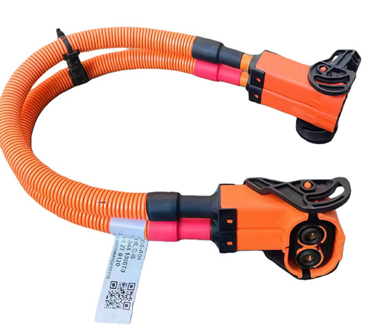
New energy cables serve different electrical jobs, including power transfer and control signals in electric and hybrid vehicles. This discussion follows the power path: battery, inverter, motor and charging equipment. A high voltage wire harness connects these components, but its voltage capability alone does not tell an engineer how efficiently current reaches them.
Resistive loss occurs in both the conductors and their connections. A power path includes cable resistance, conductor-to-terminal joints and mating contacts. For a simple DC circuit, the voltage drop is current multiplied by resistance; the heat dissipated is current squared multiplied by resistance, or P = I²R.
Current therefore matters twice in the heating calculation. Doubling current produces four times the resistive loss if resistance stays unchanged. That is why a connection that seems unremarkable at light load can deserve attention during sustained high-current operation.
Why a small contact resistance matters
A milliohm-scale difference becomes tangible when expressed in watts. Consider one connection carrying a steady 200 A. The following values are illustrative assumptions, not measured product results, specified acceptance limits or predictions of vehicle range.
|
Assumed connection resistance |
Voltage drop at 200 A |
Heat at 200 A |
|
0.2 milliohm (0.0002 ohm) |
0.04 V |
8 W |
|
1.0 milliohm (0.001 ohm) |
0.20 V |
40 W |
The higher-resistance example dissipates an additional 32 W at that one connection. The calculation uses V = IR and P = I²R, with identical current in both cases. It explains why a small resistance increase deserves attention without assuming that either value represents an acceptable production connector.
Localized heating and whole-vehicle energy consumption require different conclusions. Forty watts concentrated at a connection raises a thermal design question, but a battery-range estimate also needs the operating time, current profile and other vehicle losses. One contact measurement cannot supply that missing context.
How cab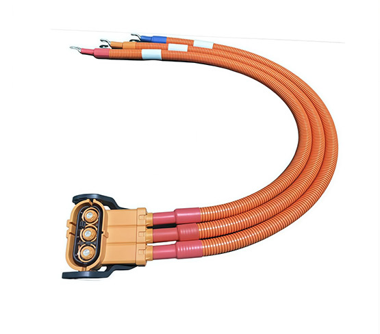 le size and terminals share the loss
Conductor resistance sets the background against which connection losses must be judged. At the same material and temperature, resistance rises with conductor length and falls as cross-sectional area increases. Increasing the size of high voltage automotive cable addresses the cable portion of the loss; it does not repair a poorly matched terminal joint.
The cable and connector must therefore be considered as one electrical path. Songyuan wiring harness offers a high-voltage EV assembly family with the customization ranges below. They describe available design choices across the family, not one configuration that delivers every maximum simultaneously.
|
EV assembly parameter |
Customization range |
Meaning for loss assessment |
|
Conductor cross-section |
6-150 mm² |
Compare resistance at the actual selected size. |
|
Cable length |
1-15 m |
Include the complete circuit path in the calculation. |
|
Current |
50-800 A |
Establish the selected configuration’s operating conditions. |
|
Voltage |
DC 600-2000 V |
Check voltage suitability separately from resistive loss. |
The practical comparison uses a defined assembly, not the widest available range. A longer route and a different terminal selection can change the result even when the conductor material is unchanged. In an automotive wire harness, each high-current branch needs its own current and resistance assumptions.

Why connection quality has to last
A sound crimp depends on matching the conductor cross-section, crimp contact and tooling. The joint links the cable to the terminal, while the mating interface forms a separate connection. Checking only one leaves part of the electrical path unexplained. This distinction matters when comparing complete assemblies with connector-only specifications.
Production consistency helps preserve that match across a batch. Crimping tools wear, so production monitoring matters even after a suitable combination has been selected. The EV assembly family includes high-voltage crimp terminals and sealed connector options; those choices still need an application-specific definition before their electrical performance can be compared.
Operating temperature also changes the comparison. Copper resistance increases as temperature rises, so a cold resistance measurement is not a complete account of losses during operation. Routing that avoids hot areas and moving components helps address the thermal and mechanical conditions around the connection.
What an efficiency claim needs to demonstrate
A useful custom wire harness comparison holds the relevant conditions steady. Engineering teams should identify the exact conductor, route length, terminal pair, current profile and temperature used in each result. Otherwise, a claimed improvement may reflect different test conditions rather than a better connection.
Electrical and thermal results answer complementary questions. Resistance or voltage-drop measurements quantify the electrical loss; temperature measurements help evaluate where heat accumulates in the installed arrangement. For a repeated-load application, the review should cover the intended duty cycle and the connection after relevant environmental and mechanical conditioning.
Performance language should follow the evidence. A documented reduction in connection loss supports that specific claim. It does not by itself establish a percentage improvement in total vehicle efficiency, and neither a high voltage rating nor a larger conductor supplies the missing system-level measurement.
Lower losses depend on the complete connection
Efficient EV power delivery depends on controlling resistance through the cable, its terminations and its mating contacts. The strongest comparison defines the current, route and operating conditions, then explains the electrical loss and resulting heat. For trade teams, that creates a clear way to discuss connection performance without turning a component specification into an unsupported vehicle-efficiency promise.
FAQ
Are new energy cables only high-voltage power cables?
No. EV wiring also includes lower-voltage control and communication circuits. Their design priorities differ, so power-loss conclusions for high-current branches should not be applied automatically to signal wiring.
Does a higher voltage rating mean lower cable losses?
No. A voltage rating addresses voltage suitability. Resistive loss depends on the current and resistance of the actual circuit; the rating alone provides neither value.
Can thicker cable compensate for a poor connector?
It can reduce the conductor’s contribution to resistance, but it does not correct the separate resistance of the joint or mating contact. Both need assessment.
Why compare resistance at operating temperature?
Copper resistance changes with temperature. Measurements taken under comparable thermal conditions make loss comparisons more meaningful than comparing an unloaded cold assembly with a warm operating one.
Can a connector upgrade guarantee longer EV range?
No. Lower connection loss may help power delivery, but range depends on the full vehicle and its driving conditions. A range claim needs evidence beyond connector specifications.


