

Energy Storage Wiring Harnesses: Power and Sensing
Time : November 12, 2026 View : 133
A battery cabinet can have a sound power connection and still deliver unusable cell readings. Follow the heavy leads and you reach the charging or discharging path. Follow a small sampling branch and you reach a cell tap or temperature sensor. Your team needs both paths on the drawing, with enough detail to tell a misplaced signal lead from a poor power connection.
Three circuits with different jobs
During charging, current enters the battery through the power connections. During discharge, those connections carry current out to the load. Size the conductor for the specified electrical duty, then check whether the termination and route fit the installation. A sampling branch has another job: it carries the information used to supervise the battery. Protective earth, or PE, connects designated conductive parts to the equipment’s protective grounding arrangement.
Our battery wiring harness range at Songyuan wiring harness includes battery signal acquisition lines, PE lines and CCS modules. Those names identify different connection functions. Keep PE identified separately on your schematic. Giving it a signal-return label, or assigning a sampling branch to the charging path, changes the function of the connection.
On the assembly drawing, name the two endpoints of each branch and what passes between them. This also makes inspection more precise. Continuity between two intended pins answers a different question from whether a protective connection or loaded power termination meets its engineering requirements.
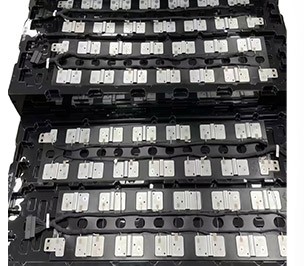
Cell readings depend on the complete sampling path
The BMS connector brings several kinds of information to one board. A cell tap, a temperature sensor and a communication branch need separate interface definitions even when all three enter the same enclosure. The harness transmits these signals; the monitoring electronics interpret them and implement the specified protection functions.
For a concrete electronics example, consider Texas Instruments’ BQ76952. This monitor and protector serves 3-series to 16-series battery packs. Its listed functions include open-wire detection, temperature sensing and voltage protection. Those functions reside in the monitoring device. Matching a harness to that device still requires the appropriate circuit and pin definitions.
Pin order matters because the connector shell alone does not identify the measurement point. Your drawing needs to connect a named cell or sensor to a named input. Marking a branch only as “battery signal” leaves too much unresolved when several similar plugs meet inside one cabinet.
Our storage-battery signal acquisition line offers branch lengths within a 0.3–20 m customization range and conductor options from 24AWG to 16AWG. These are available configuration ranges, not a recommendation to use the longest branch or largest conductor. The chosen BMS interface, module positions and routing determine which combination belongs in your assembly.
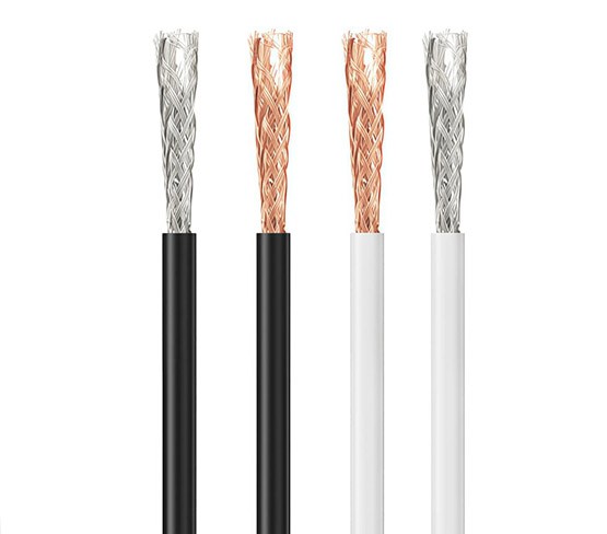
Routing decides where shielding earns its place
Sampling wires may share a cabinet with a converter and its power connections. That layout makes the route part of the signal design. Review where sensitive branches run, where the loom crosses power wiring and how the connection reaches the monitoring board.
A shielded wire harness offers a way to address interference where the circuit calls for it. We offer braid, foil and double-layer constructions. Which connection does the shield make at the cable end? Put that detail on the drawing. Without it, the assembly instruction identifies the shielding material but leaves its termination undecided.
Shielding does not correct a swapped cell lead or a loose terminal. Keep those fault paths separate during troubleshooting. If a channel reads steadily until the converter operates, compare the two operating conditions before changing the cable. For a channel that remains absent with the converter idle, begin by checking the intended signal path. Keep both observations in the fault record so you can test possible causes without prematurely blaming interference.
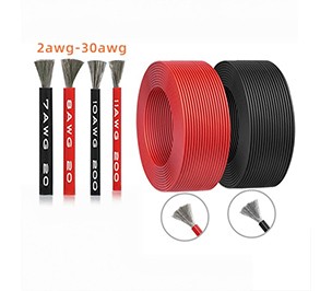
Flexible wire still needs a workable installation
A tight connector exit leaves little room to dress the wires. Our silicone rubber insulated wire uses fine stranded conductors for flexibility, giving your team an option to consider where a connection needs to bend into position. The wire still needs room, support and protection at edges. Soft insulation does not establish current capacity or a permissible bend radius.
Our extra-soft silicone wire specifications show why the outside diameter deserves attention:
|
Wire option |
Specified outside diameter |
Installation implication |
|---|---|---|
|
20AWG |
1.8 ± 0.1 mm |
Check the terminal’s insulation support range. |
|
16AWG |
3.0 ± 0.1 mm |
Allow room through sleeves and connector exits. |
|
10AWG |
5.5 ± 0.25 mm |
Recheck bundle clearance and available routing space. |
These dimensions describe those wire options, not a completed storage harness rating. Before approving a gauge change, compare the new wire with the terminal dimensions and any seal that grips the insulation. Leave enough space for the changed bundle to reach its connector without crowding the exit.
Inspection follows the circuit’s purpose
Your inspection plan should preserve the distinction between power, sampling and PE. For sampling branches, verify the complete pin-to-point map and branch identification against the approved drawing. Check terminal seating and support where a branch leaves the main loom.
Power and protective connections need acceptance criteria set by the equipment design. A continuity indication alone does not establish loaded temperature rise, insulation suitability or protective bonding performance. Record the required method and limits rather than asking one generic “electrical test” to cover every function.
Changes need the same discipline. If a module moves, review branch reach, connector access and strain relief together. Check where the extra wire will sit: a branch that now reaches its connector may also hang loose against a cabinet edge.
A useful harness specification separates the functions
Use the drawing to trace the connection you need to investigate. For a suspect cell reading, that means following the sampling branch to the named cell tap. For PE, find the designated bonding point and its acceptance requirement. Your team can then discuss a missing reading, a crowded connector exit or a protective connection as a specific engineering issue.
For a storage assembly discussion, share the module arrangement and BMS pin definitions with our team so we can review the corresponding acquisition and PE connections.
FAQ
Does a battery sampling harness carry charging current?
Its intended role is measurement and related signals. Give the charging-current leads their own specification. Check the intended circuit before replacing any branch that happens to use a similar-looking plug.
Is CAN wiring the same as a cell voltage lead?
No. A CAN branch carries messages between connected electronics. A cell voltage lead reaches a particular measurement point. Identify that function on your pinout; the plastic connector housing cannot tell an assembler which circuit is inside.
Can a shield replace protective earth?
A signal shield and PE serve different purposes. Check the grounding and bonding drawing for each connection. It needs to identify the shield termination and the designated protective earth path separately.
Does thicker silicone insulation prove a higher voltage rating?
Outside diameter alone cannot establish that rating. Confirm the specified insulation system and applicable electrical requirements for the actual wire and assembly.
What information resolves an ambiguous replacement branch?
Use the approved pinout, mating connector identification, wire specification and branch dimensions. A photograph helps identify the layout but cannot establish the electrical connections concealed inside it.


