
How an Automotive Wire Harness Connects EV Systems
Time : September 23, 2026 View : 240
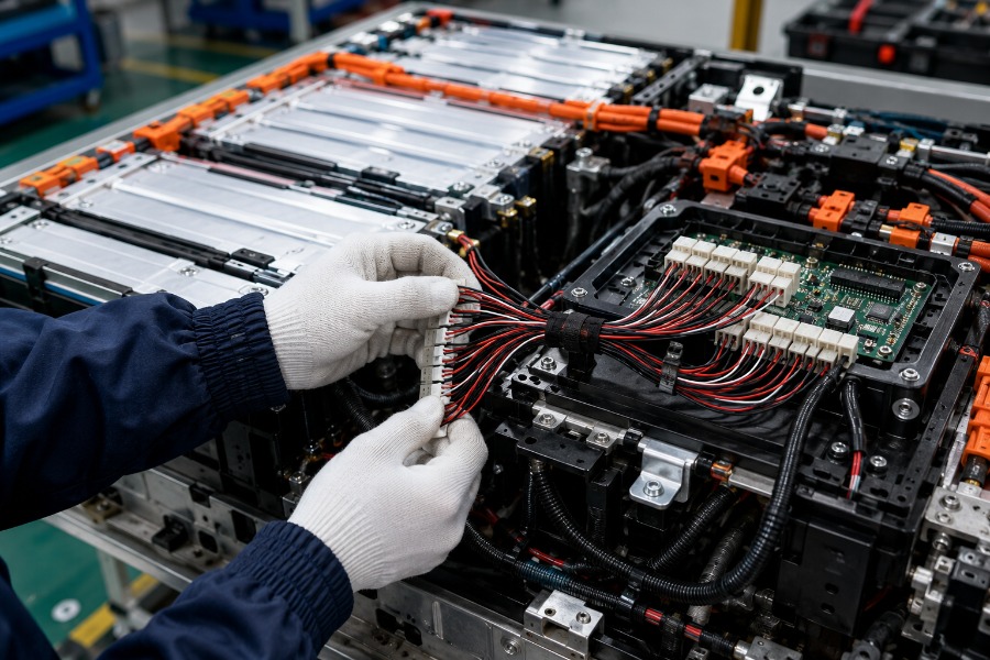
An EV’s battery-to-motor connection tells only part of its operating story. Component distributors and vehicle integration teams also need to follow the smaller circuits carrying measurements and commands. An automotive wire harness links these power and information routes, allowing separate modules to work together while each retains its own electrical or control function.
Battery Power Branches Toward Drive and Auxiliaries
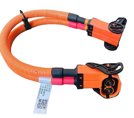
The traction battery supplies energy through several branches with different destinations. During driving, high-voltage cables connect the battery pack to the inverter, which converts DC into the AC supply used by the drive motor. The cable between inverter and motor therefore carries the inverter’s output, rather than an unchanged battery supply.
The DC/DC converter creates another branch into the vehicle’s lower-voltage network. It reduces the traction battery’s DC voltage to a level suitable for accessories and the auxiliary battery. Lights and control electronics can consequently receive their appropriate supply while propulsion uses a separate power path.
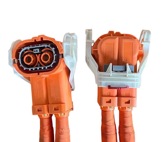
A high voltage wire harness provides connections among these power components. The conductors carry electrical energy, while the inverter and converter change its form or voltage. Identifying the component at each end explains what a branch does more clearly than treating every large cable as a battery lead.
BMS and Controllers Close the Information Loop
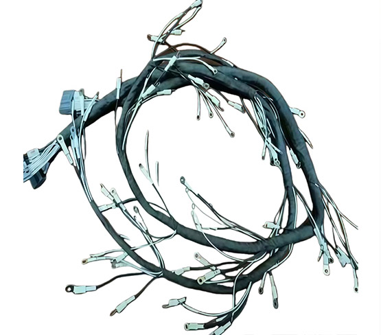
Power delivery depends on information about the battery and the vehicle’s operating needs. Cell-voltage and temperature sensing connections provide measurements for the battery management system, or BMS. These measurement circuits have a different job from the communication link through which the BMS exchanges information with other control units.
The BMS connects battery information to decisions elsewhere in the vehicle. Networks such as CAN allow communication with the vehicle control unit, charger and other relevant systems. The vehicle control unit, or VCU, may coordinate torque, charging and thermal functions; the precise allocation of those responsibilities depends on the vehicle architecture.
A temperature response illustrates this relationship between sensing and control. In one possible arrangement, a temperature measurement reaches the BMS, battery status passes to the VCU, and a controller adjusts the cooling response. The harness carries the measurements and messages through this chain; the electronics interpret them and determine the response.
The signal branches of an automotive wire harness therefore need identifiable endpoints. A cell-sensing lead and a CAN communication pair may both relate to the battery, but they serve different interfaces. Keeping that distinction clear helps component teams understand how a battery assembly participates in the wider control system.
Charging Creates a Different Route Into the Battery
Charging changes the direction and entry point of the energy flow. During AC charging, the vehicle inlet connects to the onboard charger, or OBC, which converts incoming AC into DC for the traction battery. DC fast charging supplies DC through its charging path and bypasses the OBC’s AC-to-DC conversion stage.
Communication remains part of charging even when the conversion route changes. The charging system must coordinate delivered power with battery condition and applicable limits. A power connection alone does not provide the information needed for that coordination, so the inlet and charging electronics also require their specified communication connections.
One inlet assembly consequently accommodates circuits with different electrical roles. Songyuan wiring harness offers a new energy vehicle AC charging socket wiring harness assembly connecting the inlet with the OBC and associated VCU/BMS interfaces. Its customization ranges illustrate how power conductors, communication wires and physical reach are treated separately.
|
Function |
Available Configuration |
Meaning for the Connection |
|
AC charging power and current |
3.3-22 kW; 16-32 A |
The combination depends on supply voltage and phase arrangement |
|
Power conductor cross-section |
1.5-6 mm² |
Power connection sized for its particular circuit |
|
Communication conductor size |
24-16 AWG |
Separate conductors carry charging signals |
|
Assembly length |
1-5 m |
Length and branches accommodate the vehicle layout |
These ranges apply to that AC charging socket assembly family, with the final combination determined by the vehicle circuit design. They are not simultaneous ratings for every configuration. In particular, conductor size must suit the circuit and operating conditions; increasing cable size does not increase the OBC’s conversion capability.
Shared Interfaces Keep the Paths Working Together
The meeting points between circuits make connector details significant. Physical mating, pin assignments and electrical ratings answer different questions: whether parts fit, which circuit reaches each terminal, and whether the connection suits that circuit. Similar-looking connectors cannot establish all three. The full connection must match the function at both ends.
Component packaging can also change where these connections appear. A PEU-specific harness links the power electronic unit with the battery, drive motor, OBC and DC/DC converter, supporting power and control connections. Combining functions in an integrated unit changes the external arrangement without removing the need for those electrical functions.
A custom wire harness can place branches and interfaces around that arrangement. Route lengths and branching must suit the actual endpoints, while shielding and grounding address electromagnetic coupling where the circuit design requires them. These choices connect the power and information paths physically without making their electrical requirements interchangeable.
Every Connection Has a System Role
An EV harness is easiest to understand by tracing what travels through each branch and where it goes. Driving links battery energy to propulsion and auxiliaries; charging creates a route back into the battery; sensing and communication support the controllers in both modes. For integration teams, that functional map provides the basis for understanding each assembly’s interfaces.
FAQ
What distinguishes high-voltage and low-voltage harness functions?
High-voltage branches serve propulsion and other loads designed for that supply. Lower-voltage branches serve electronics, accessories and control connections. A single vehicle needs both, with conductor and interface requirements determined by the role of each circuit.
How does the BMS communicate with other vehicle systems?
The BMS exchanges information over vehicle networks such as CAN. Its communication link is separate from the cell-sensing connections used to collect measurements. Message content, connected controllers and control responsibilities depend on the vehicle architecture.
Do AC and DC charging use the same power route?
AC charging routes power through the OBC’s AC-to-DC conversion stage. DC fast charging bypasses that stage and delivers DC through the vehicle’s DC charging path. Both still require coordination with the battery and charging controls.
Why does an EV need a DC/DC converter connection?
The traction battery’s voltage differs from the supply required by lower-voltage accessories and the auxiliary battery. The DC/DC converter connects those networks by changing the voltage. Harness branches carry its input and output to their respective destinations.
Can a connector that fits replace the original connection?
Physical fit alone does not establish interchangeability. Pin functions, electrical ratings and the mating interface must also match the intended circuit. An apparently identical housing can carry a different assignment of power or signal connections.