

How Does a New Energy Vehicle Wiring Harness Control EMI?
Time : August 27, 2026 View : 292

A sensor that behaves normally at idle but faults during acceleration or fast charging often points to a coupling problem, not a failed sensor. In a new energy vehicle wiring harness, high-voltage power and low-voltage data share a crowded vehicle, so current changes can disturb nearby signals. The useful question is not whether electromagnetic interference exists. It is where the noise enters, how it returns, and which design change removes the path without making the harness heavier than necessary.
Why the Fault Appears Only Under Load
Electrical noise becomes visible when the powertrain changes state. A traction inverter switches current rapidly, a motor draws more torque, or an onboard charger changes phase. Those changes create fields around the power conductors. If a signal circuit runs beside them for long enough, unwanted energy can appear as voltage on the signal pair. The symptom may be a sensor spike, a communication retry, or a fault code that disappears at steady load.
The power loop is noisy by nature
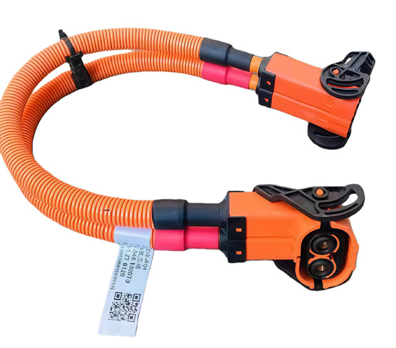
A high voltage wire harness carries substantial current between the battery pack, inverter, drive motor, OBC, and high-voltage distribution points. Fast current transitions matter as much as current level because a steep edge contains higher-frequency energy that couples more easily into adjacent conductors. Larger conductors reduce resistive loss, but conductor size alone does not control radiated noise. Loop area, cable spacing, connector geometry, and the continuity of the return path determine how much field reaches a nearby circuit.
The signal loop fails for a different reason
Low-voltage circuits carry small signals that leave less margin for unwanted voltage. Battery sampling, temperature sensing, CAN communication, and resolver or position feedback can all be affected when routing, shielding, or grounding is weak. A new energy vehicle high and low voltage wiring harness therefore needs deliberate separation between power and data paths. The goal is not perfect silence. The goal is enough signal margin that normal power switching cannot push a valid message or measurement outside its acceptance window.

Where EMI Enters the Harness
Interference rarely comes from one dramatic mistake. It usually enters through a small set of repeatable paths, and each path leaves a different clue. Matching the symptom to the likely coupling route prevents a team from adding shielding everywhere while the actual fault remains at a connector, branch point, or ground termination.
|
Observed condition |
Likely coupling path |
Typical symptom |
First check |
|
Fault rises with motor torque |
Magnetic coupling from the power loop |
Sensor value shifts under load |
Parallel run length and loop area |
|
Fault begins during charging |
Common-mode current through grounds |
CAN errors or unstable readings |
Shield and ground termination |
|
Fault follows connector movement |
Discontinuous shield or return path |
Intermittent noise bursts |
Connector shell and drain continuity |
|
Fault appears after rerouting |
Signal cable moved near a switching node |
Repeatable issue in one operating state |
Branch location and spacing |
How to Quiet the Harness Without Adding Bulk
A focused correction starts with the coupling path, not the thickest material. Separation reduces electric and magnetic coupling, while short parallel runs limit transfer distance. Twisting a signal pair helps the receiver reject common noise. These choices often improve more than adding another layer to a poor layout.
Shielding must form a complete path
A shielded wire harness works only when the shield is continuous through branches and connectors and has a defined termination strategy. A floating shield can collect noise, while a narrow or irregular connection can lose effectiveness as frequency rises. Our battery signal acquisition designs can use single-layer aluminum foil or double-layer shielding with a grounding lead, and we reserve the stronger arrangement for routes near motors and inverters. That keeps the response tied to the actual field exposure rather than applying the same construction everywhere.
Routing should be settled before extra material
Harness geometry decides whether shielding has a manageable job. Power and signal branches should diverge early, cross at a broad angle when they must meet, and avoid long shared clips or channels. Connector transitions deserve the same attention because a well-shielded cable can become vulnerable where the braid stops too early. For a new energy vehicle power battery wiring harness, the practical review should include these points:
*Keep sensitive signal pairs away from inverter phase cables and other switching nodes.
*Minimize loop area by keeping each circuit close to its intended return conductor.
*Maintain shield continuity through connector shells, splices, and branch breakouts.
*Separate mechanical protection decisions from electrical shielding decisions.
What to Verify Before Release
A useful verification plan reproduces the operating state that caused the concern. A continuity check confirms wiring, but it cannot show what happens when the inverter switches under load. Compare quiet and noisy states, then watch the affected signal, bus error count, and voltage between intended ground points while changing one routing or termination variable at a time.
A second check should examine the physical harness after electrical results improve. At Songyuan wiring harness, we can configure low-impedance conductors, sealed high-voltage connectors, multi-layer protection, and EMC filter components, but the layout must still avoid moving parts, heat sources, and unnecessary parallel runs. Release decisions should reflect the real branch locations and connector interfaces, not only an open bench sample.
The Practical Takeaway
EMI control in an automotive wire harness is mainly a path-management problem. High-voltage switching creates the field, but spacing, loop area, shield continuity, grounding, and connector transitions decide whether that field reaches a sensitive circuit. When a fault appears only during one vehicle state, reproduce that state, identify the coupling route, and change the smallest relevant design variable. A quiet harness is usually the result of several ordinary decisions made consistently, not one oversized layer added at the end.
When an EV program has a repeatable noise symptom, we can review the power and signal branch relationship and help translate the finding into a manufacturable harness layout.
Preguntas frecuentes
Can shielding alone stop EMI in an EV harness?
Shielding can reduce coupled energy, but it cannot repair poor routing, a large loop area, or an undefined ground path. Treat it as one part of the current-return and layout strategy.
How far apart should high-voltage and signal cables be?
There is no universal distance because voltage, current edge rate, parallel length, shielding, and receiver immunity all matter. Use the largest practical separation, then verify it in the real operating state.
Why does interference appear only during acceleration or charging?
Those states change current quickly and activate switching devices that may be quiet at idle. The stronger or faster-changing field exposes a coupling path that is invisible during steady operation.
Does a larger conductor reduce signal interference?
A larger conductor can reduce voltage drop and heat, but it does not automatically shrink loop area or improve shield termination. EMI performance still depends on geometry and the return path.
What should be checked first for an intermittent sensor fault?
First correlate the fault with vehicle state. If it follows torque, charging, or another switching event, inspect parallel routing, connector shield continuity, and ground potential before replacing the sensor.


noticias relacionadas
-
 How Does a Medical Wire Harness Fail After Cleaning
-
 What Is a Medical Wire Harness?
-
 ¿Cómo contribuyen los cables y arneses de cableado personalizados al diseño de electrodomésticos inteligentes?
-
How Does a New Energy Vehicle Wiring Harness Control EMI?
-
 ¿Cómo se equilibra el peso y el ancho de banda en el diseño de cables para drones?
